UCA / SYSTEM-LEVEL CONTINUITY
Unified Continuity Architecture™
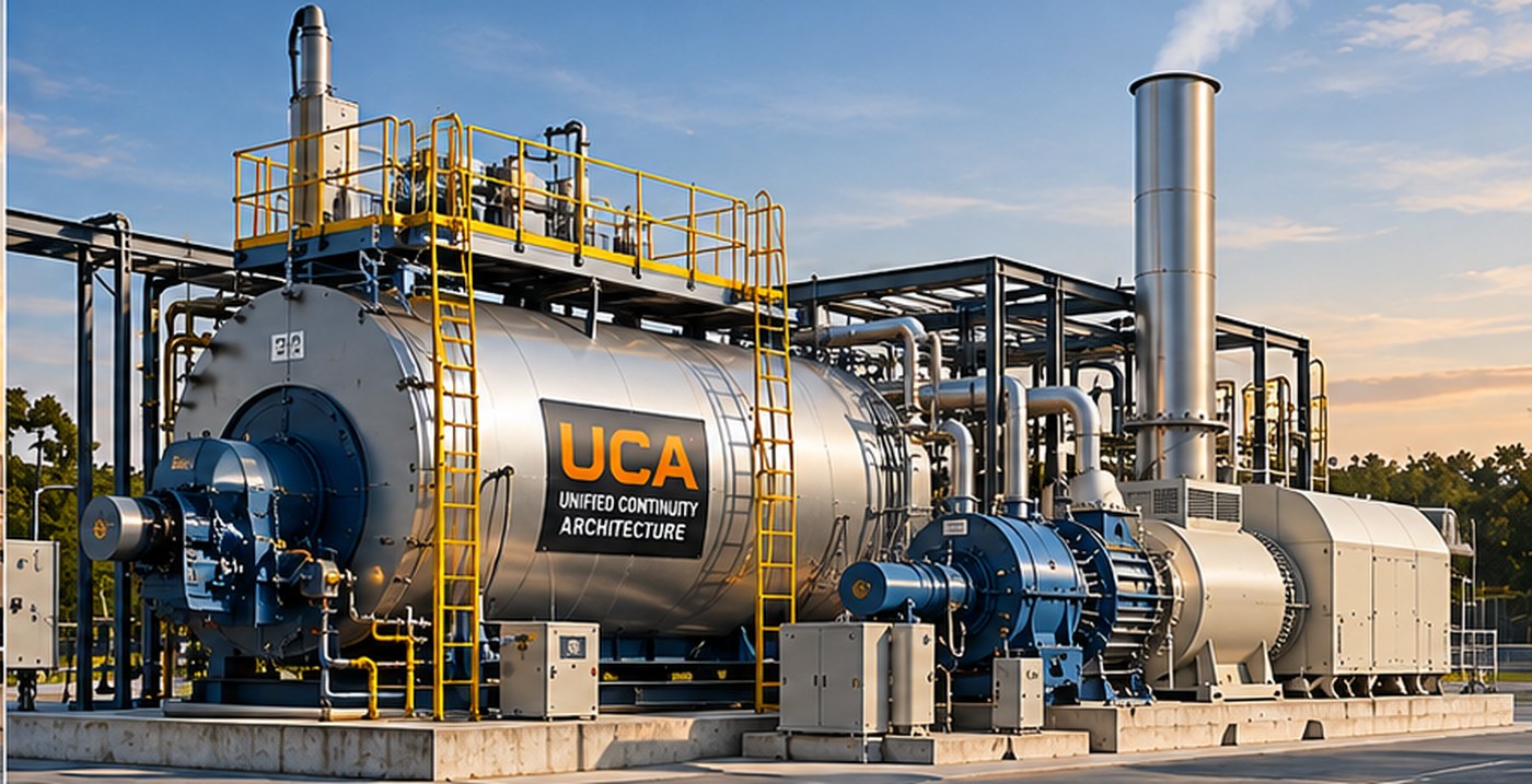
Coordinating primary generation, stored-energy shaft reinforcement, rotational inertia and standby functionality as elements of a unified power system.
Coordinating primary generation, stored-energy shaft reinforcement, rotational inertia and standby functionality as elements of a unified power system.
The Unified Continuity Architecture™ expands the concept into an integrated system coordinating synchronized generation, rotational inertia, stored-energy shaft reinforcement, primary generation and standby functionality. Keeping generation in motion provides the foundation for coordinated ride-through and frequency support.
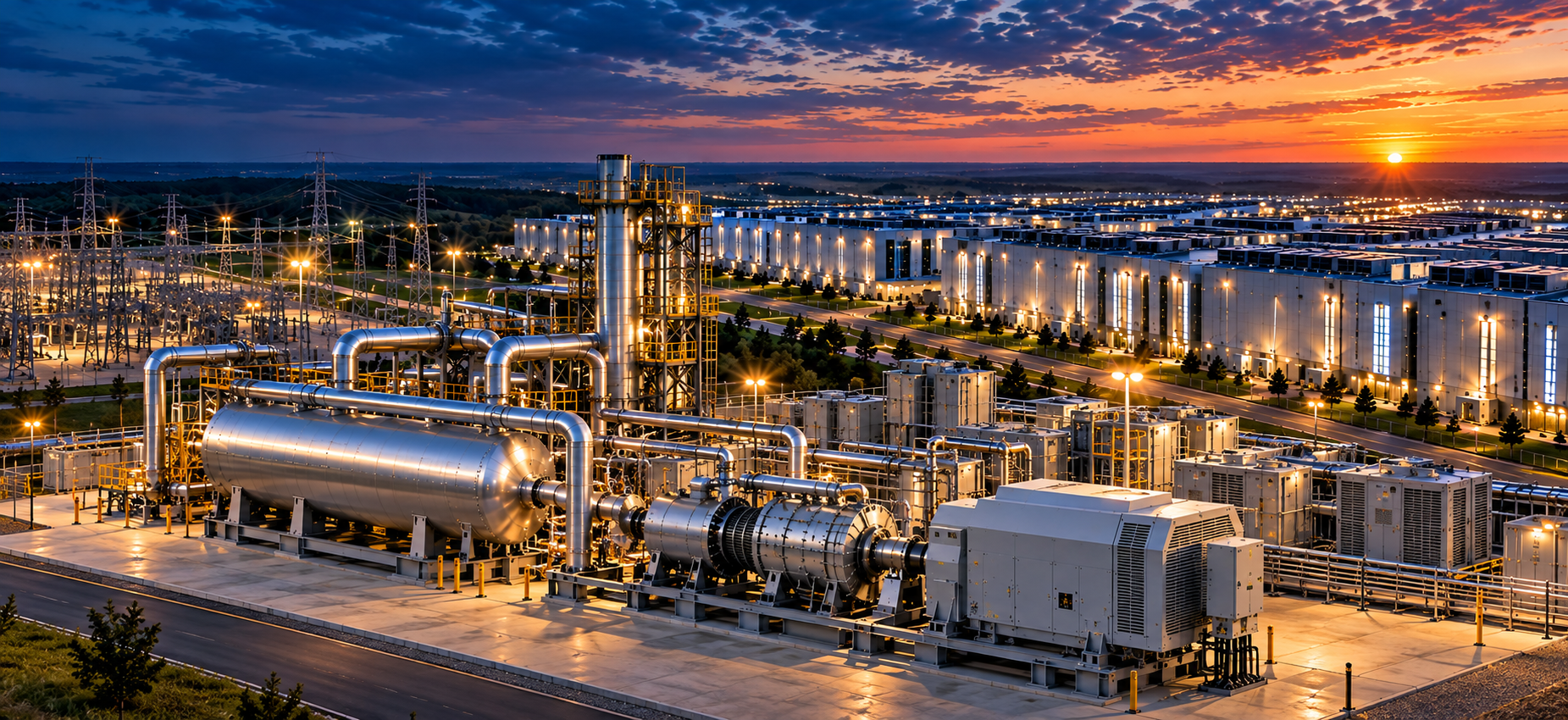
Conceptual visualization of an integrated mission-critical generation campus.
One architecture. Multiple layers of continuity.
Stored thermal energy and steam generation can naturally coexist within an Impulse Inertia architecture, creating an integrated approach to generation and continuity.
Impulse Inertia can reinforce synchronized rotating generation while a reciprocating engine, combustion turbine or other primary motive source transitions or assumes load.
Unified Continuity Architecture™ changes the starting condition. During normal utility or external-power availability, a synchronous electrical machine operates as a motor and maintains its shaft train in rotational readiness. On a qualifying power interruption, the same machine transitions to generator operation. Existing kinetic energy and a stored-energy-fed auxiliary steam turbine provide the immediate mechanical bridge while the primary prime mover starts or transitions to combustion-powered operation.
Disconnect the engine during standby to avoid its compression, friction and pumping losses. Keep the generator and auxiliary steam turbine rotating, then start the engine independently and couple it when ready.
Explore the clutched engine →Keep the combustion-turbine rotor mechanically connected and spinning as useful inertia, while lowering gas-path pressure to reduce aerodynamic drag and standby power consumption.
Explore the turbine concept →A conventional standby engine-generator set must start its engine and accelerate the attached generator from rest. In this embodiment, the synchronous generator is already rotating at a predetermined standby speed, powered as a motor by the external electrical source. A directly connected auxiliary steam turbine also rotates with it. The reciprocating engine, however, remains stationary behind an open clutch.
External power operates the synchronous machine as a motor. The generator rotor and steam turbine remain at speed; the engine is isolated by the disengaged clutch.
When external power is lost or degraded, the synchronous machine transitions to generator operation. The spinning shaft supplies initial kinetic energy.
Stored steam or other motive-fluid energy drives the auxiliary turbine, applying supplemental shaft torque to counter speed and frequency decay.
The reciprocating engine starts and accelerates without having to accelerate the generator rotor and directly coupled auxiliary turbine from rest.
After engine speed, direction, torque and other permissives meet the design criteria, the clutch engages under a controlled sequence to limit torsional shock and speed disturbance.
The engine progressively assumes the generator's mechanical load while auxiliary steam-turbine torque is reduced. Following restoration, the system can return to motor-driven standby.
Possible couplings include controlled friction, wet, multidisc, hydraulic, electromagnetic or synchronized arrangements, subject to torsional analysis and engagement controls. Exact time to load acceptance depends on the engine, clutch, shaft system and stored-energy capacity.
The second embodiment makes a different engineering choice: rather than disconnecting the prime mover, it intentionally keeps the combustion turbine's compressor, turbine rotor, shafting and generator rotating together. That additional rotating mass becomes part of the stored inertia available during a disturbance.
Importantly, inertia does not create energy or indefinitely maintain generator output. It slows the rate of speed decay; the duration of support depends on total stored kinetic energy, allowable speed deviation, electrical loading, and the prompt availability of auxiliary shaft torque. The added rotating mass is valuable precisely because it provides an immediate mechanical response before a combustion system can begin producing sustained power.
Ordinarily, spinning compressor and turbine blading through atmospheric-density gas imposes windage, ventilation, aerodynamic drag and pumping-related standby losses. Patent #2 describes isolating at least part of the gas path with suitable inlet/exhaust valves, shutters or dampers and using a pressure-reduction system to maintain that region below ambient atmospheric pressure while the turbine remains in rotational standby.
External electricity motors the synchronous machine, keeping the combustion-turbine rotating assembly and auxiliary turbine at a predetermined standby speed.
Gas-path isolation devices separate selected turbine passages from ambient atmosphere. A vacuum or pressure-reduction device reduces gas density and aerodynamic resistance.
Following an unacceptable power disturbance, the combined inertia of the already-rotating combustion-turbine compressor, turbine rotor, shafting and generator immediately resists deceleration and slows the initial frequency decline as the synchronous machine transitions to generator operation.
The auxiliary steam turbine supplies temporary torque to counter the decelerating load and support electrical frequency.
Controls admit or equalize air, restore appropriate gas-path conditions, and manage the changing compressor drag while maintaining the required shaft speed.
After the turbine's required startup permissives and combustion conditions are satisfied, the combustion turbine fires and progressively assumes sustained generator load; auxiliary torque is reduced.
The patent describes possible pressure-reduction equipment including vacuum pumps, ejectors and liquid-ring vacuum pumps, together with controlled inlet, exhaust, equalization or bypass devices. An optional clutch may isolate the combustion turbine during selected transition phases, depending on the implementation.
“Reduced-pressure” refers to the gas-path environment during standby not low-oxygen combustion or an assertion that a turbine can safely fire under vacuum. Restoring appropriate air supply, pressure and all OEM safety interlocks is essential before combustion.
Both configurations combine a synchronous motor-generator already at speed, kinetic energy stored in rotating equipment, and an auxiliary turbine driven by stored energy. The auxiliary turbine is not the long-term prime mover: it provides controlled supplemental torque while the reciprocating engine or combustion turbine becomes capable of carrying the load.
For a synchronous generator, electrical frequency tracks rotor speed. Supplemental shaft torque can help reduce the rate and depth of speed decline during the transition, subject to available energy and control response.
The generator need not start from rest after the event. The engine embodiment isolates the stopped prime mover; the turbine embodiment retains rotating mass with reduced gas-path drag.
Unlike diesel reciprocating generators, which rely on rapid, intermittent combustion at high temperatures and pressures, an oil-fired packaged steam boiler employs continuous, controlled combustion.
Even when burning the same No. 2 diesel fuel, a properly engineered and tuned boiler offers the potential for reduced visible smoke, soot, unburned hydrocarbons and exhaust odors compared with conventional diesel engines without advanced emissions aftertreatment. Burner design allows precise control of fuel atomization, air-to-fuel ratio and flame characteristics.
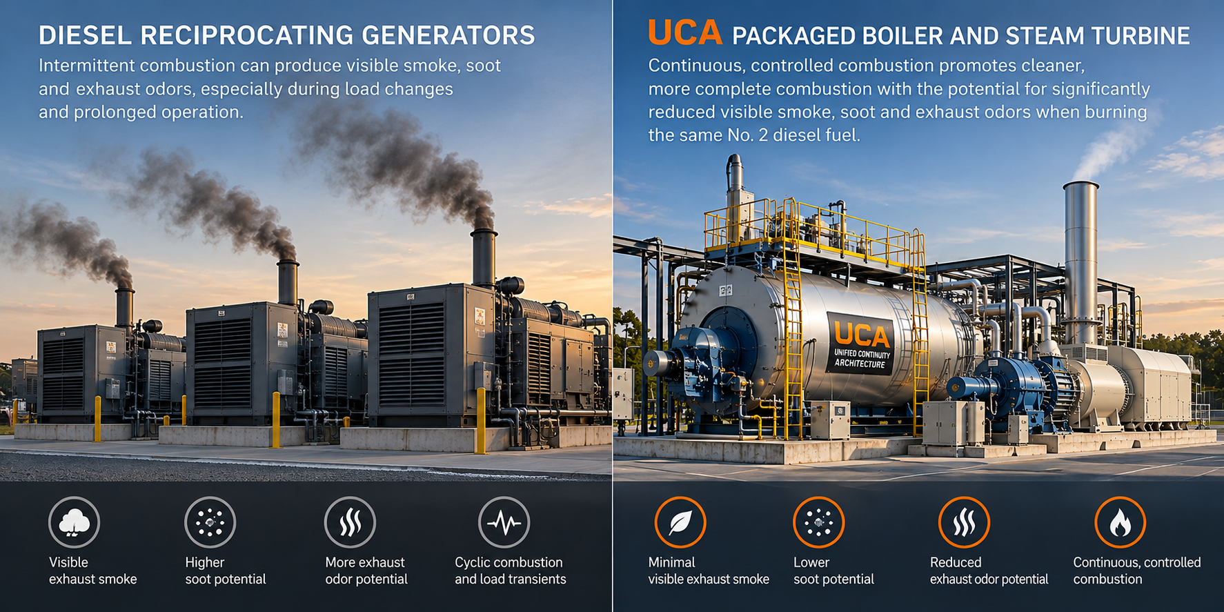
Illustrative concept, not a measured emissions test. Modern diesel generators equipped with particulate filters and SCR may equal or outperform an uncontrolled boiler on particular pollutants. Lower visible smoke does not establish lower total emissions per MWh.
UCA is a flexible system architecture; not every configuration necessarily uses a boiler or steam turbine. The cleaner-combustion opportunity applies specifically to steam-based, oil-fired configurations.