TECHNOLOGY / SHAFT-LEVEL SUPPORT

Impulse Inertia Technology

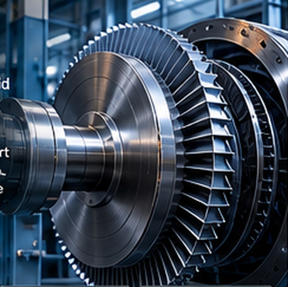
Conceptual close-up of a turbine rotor and generator shaft

Stored-energy reinforcement acts directly at the rotating shaft, supporting generator speed and electrical frequency while primary or standby motive power responds.

Frequency Support

Support the Shaft.
Support the Frequency.

For a synchronous generator supplying an islanded load, electrical frequency follows rotational speed. When demand rises faster than the prime mover can respond, the rotor gives up kinetic energy and begins to slow. Impulse Inertia is being developed to counter that deceleration with supplemental shaft torque from stored energy.

01 · Load Increase

Demand changes.
The generator is already turning.

A sudden increase in electrical load creates a temporary imbalance between the power drawn from the generator and the mechanical power supplied to its shaft.

02 · Shaft Reinforcement

Stored energy supplies supplemental torque.

When rotational decay is detected, stored energy is released through the mechanically coupled turbine. The design objective is to limit deceleration and the associated frequency decline.

03 · Prime-Mover Response

Bridge the interval.
Coordinate the response.

Supplemental mechanical power supports the transition while the prime mover increases output. During an interruption, it supports the interval while primary or standby motive power assumes the load.

One Mechanism

Direct shaft reinforcement.

Two Design Objectives

Frequency support during sudden load increases.
Electrical continuity during power interruptions.

Supplemental torque addresses deceleration. Load rejection and rising frequency require coordinated prime-mover and system controls. The response of a grid-connected system also depends on the wider network.

Impulse Inertia™

Respond to Changing Power Conditions With Power Already in Motion.

When rotational decay is detected during a power interruption or a sudden load increase, stored energy can be released through a compact turbine mechanically coupled to the rotating system. Supplemental shaft torque is designed to counter deceleration, support frequency and reinforce generation while primary or standby motive power responds.

Stored energy → supplemental shaft torque → support for rotating generation
Stored Energy
→
Impulse Turbine
→
Generator Shaft
01 · NORMALGenerator synchronized and stored-energy system charged.
02 · DISTURBANCEMotive power falls or electrical demand rises, and rotational decay begins.
03 · RESPONSEThe system detects decay and releases stored energy.
04 · REINFORCEMENTThe turbine converts stored energy directly into supplemental shaft torque.
05 · SUPPORTShaft reinforcement supports frequency and continuity while motive power responds.

Energy goes directly where it is needed: the shaft.

The Operating Principle

Direct Mechanical Reinforcement

Rotational disturbance detected
→
Stored energy released
→
Supplemental shaft torque
→
Generator rotation supported

Performance and duration depend on the engineered configuration and available stored energy. The concept is under development.

Explore Intellectual Property →